 |
| March 07, 2017 | Volume 13 Issue 09 |
Designfax weekly eMagazine

Archives
Partners
Manufacturing Center
Product Spotlight
Modern Applications News
Metalworking Ideas For
Today's Job Shops
Tooling and Production
Strategies for large
metalworking plants
Engineer's Toolbox:
6 ways to optimize part design for CNC machining
Consider hole depths, threading, wall thickness, and other machining capabilities to reduce production time and expense.
By Gus Breiland, Customer Service Engineering Manager, Proto Labs
Manufacturing prototypes and production parts fast and cost efficiently is often a balancing act of quick-turn CNC machining capabilities and an optimized part designed for those capabilities. As such, there are a handful of important considerations when designing parts for Proto Labs' milling and turning processes that can accelerate production time while reducing costs.
To fully optimize your design for machining, you should look at:
- Hole depths and diameters;
- Size and types of thread;
- Text on parts;
- Wall heights and feature widths;
- Live-tool lathes; and
- Multi-axis milling.
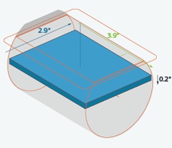
This design tip explores several CNC machining capabilities, including 3+2 machining, as shown here. This illustrates the largest part extents maximizing the raw stock of material for a part width of 2.9 in. and 0.2 in. in height.
1. The hole' truth
Anyone who has spent more than five minutes in a shop knows what a drill bit looks like and what it does. For the most part, however, holes at Proto Labs are interpolated with an endmill rather than drilled. This machining method provides great flexibility in terms of the hole sizes available with a given tool and offers better surface finish than that obtainable with a drill. It also allows us to use the same tool for machining slots and pockets, reducing cycle time and part cost. The only downside is that holes much more than six diameters deep become a challenge due to an endmill's limited length, and may require machining from both sides of the part.
2. Threading right
Drilling and thread-making go hand in hand. Many shops use "taps" to cut internal threads. Taps look like a screw with teeth, and are "threaded" into a previously drilled hole. We take a more modern approach to thread-making, using a tool called a thread mill to interpolate the thread profile. This creates an accurate thread, and a single milling tool can be used to cut any thread size that shares that pitch (the number of threads per inch), saving production and set-up time. Because of this, UNC and UNF threads from #2 up to 1/2 in., and metric threads from M2 to M12, are possible, all within a single toolset. What does this mean to you as a part designer? It means that thread-milled holes are generally limited to about 2x deep, a bit less than those that are tapped.
3. Be careful texting
Want to have a part number, description, or logo milled on your parts? The toolsets at Proto Labs are capable of machining most any text required, provided the spacing between individual characters and the stroke used to "write" them measures at least 0.020 in. (0.5 mm). Also, text should be recessed rather than raised, and it is suggested 20-point or larger fonts such as Arial, Verdana, or similar sans-serif fonts be used.
4. Tall walls and tiny features
All of our toolsets are comprised of carbide cutting tools. This super-rigid material offers maximum tool life and productivity with minimal deflection. Yet even the strongest tools deflect, as do the metals and especially plastics being machined. Because of this, wall heights and feature sizes are very dependent on the individual part geometry as well as the toolset being used. For instance, the minimum feature thickness at Proto Labs is 0.020 in. (0.5 mm) and the maximum feature depth is 2 in. (51 mm), but that doesn't mean you can design a ribbed heatsink using those dimensions. Check with us when in doubt.
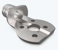
The part shown here was made with a CNC lathe with live tooling.
5. Live tool lathes
Aside from extensive milling capabilities, we offer live-tool CNC turning. The toolsets used on these machines are similar to the ones on our machining centers, except we do not turn plastic parts at this time. That means off-center holes, slots, flats, and other features can be machined parallel or perpendicular (axial or radial) to the "long" axis of the turned workpiece (its Z-axis), and will typically follow the same design rules as those applied to the orthogonal parts made on our machining centers. The difference here is in the shape of the raw material rather than the toolset itself. Turned parts such as shafts and pistons start out as round stock, while milled parts -- manifolds, instrument cases, and valve covers, for example -- typically don't, using square or rectangular blocks instead. As you'll see in a moment, however, we've broken these rules as well.
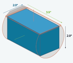
For a part using 3+2 machining, this illustrates how the part fits within a block of material using maximum part extents of 2 in. wide and 2 in. high.
6. 3+2 machining
Two distinct "flavors" of milling exist at Proto Labs. With 3-axis machining, the workpiece is gripped from the bottom of the raw material blank while all of the part features are cut from the top. Each side of the workpiece thus requires a separate setup, and with parts larger than 10 in. x 7 in. (254 mm x 178 mm), only the top and bottom can be machined: no side setups! Indexed milling, though, allows up to five sides of the workpiece to be machined in a single setup. Also known as 3+2, the part can be indexed to 90 degrees in any given angle (and at multiple, or compound, angles), allowing for complex, non-orthogonal positioning.
The toolsets used in either case are identical. What's different is the raw material. As with our lathes, round stock is used for index-milled parts, which presents some interesting mathematical discussions about the size, geometry, and positioning of the workpiece within that raw material volume (it's that whole Pythagorean theorem thing you learned in high school). For some examples of this, you can stare at the accompanying diagrams for a while, or just upload your part model online at www.protolabs.com.
As always, feel free to contact an applications specialist with any questions at 877-479-3680 or customerservice@protolabs.com.
Published March 2017
Rate this article
View our terms of use and privacy policy